
IS THE
LIMIT
operable door & window systems that have incredible
performance and superior quality.
Solar can build any type of custom structure for both
residential and commercial applications.
With our superior structure knowledge we create some of
the best openings from above in the market.
ARCHITECTURAL
GLAZING NEEDS
OF OPERABLE
& FIXED SOLUTIONS
operable door & window systems that have incredible
performance and superior quality.
CUSTOM CONFIGURED
GLASS STRUCTURES
Solar can build any type of custom structure for both
residential and commercial applications.
COSTS & ADDING
ADDITIONAL LIGHT
With our superior structure knowledge we create some
of the best openings from above in the market.


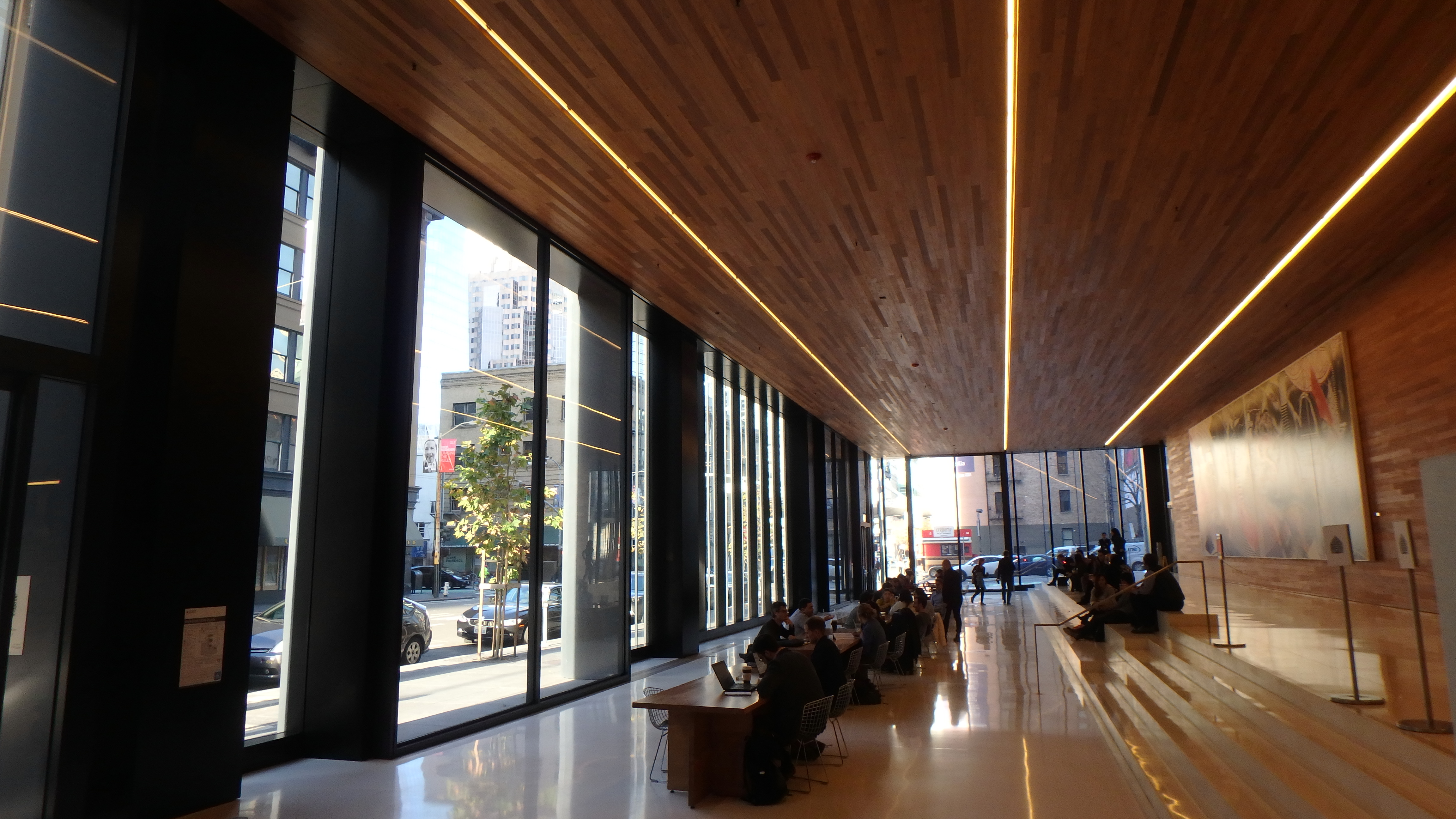
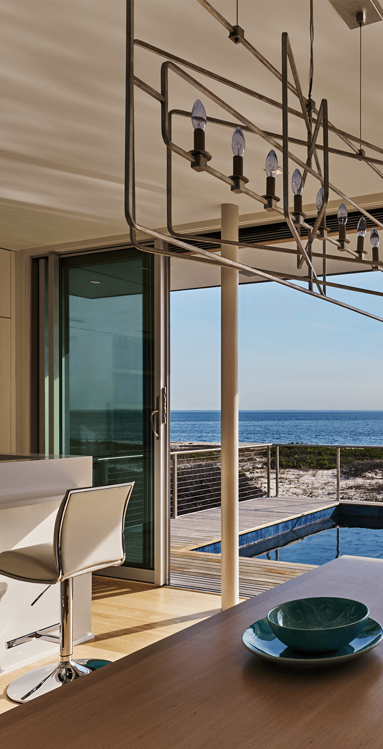
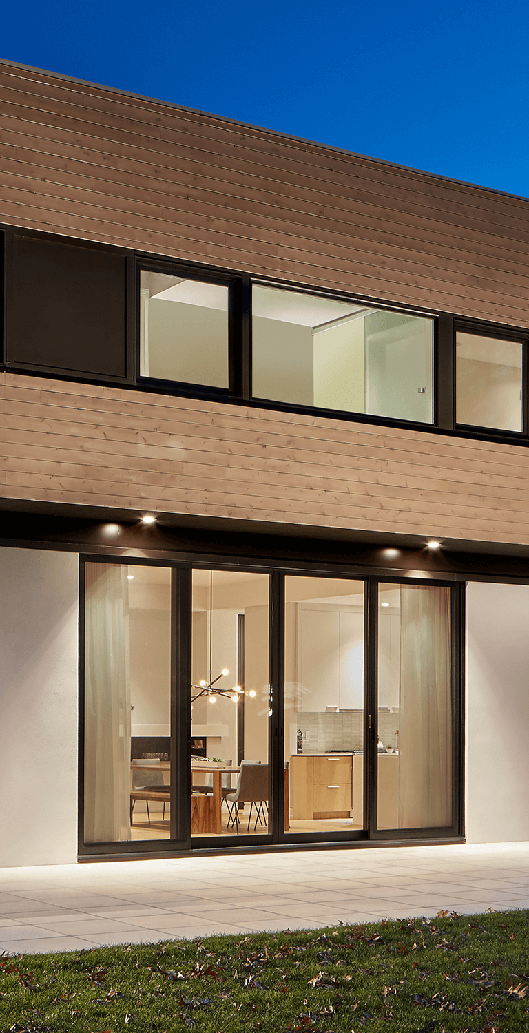
Doors & Windows
- Folding Glass Walls
- Sliding Glass Doors
- Slide & Stack Glass Walls
- Clear Glass Walls
- Lift Slide Doors
- Swing Doors
- Pivot Doors
- Curtain Walls
- Wood Curtain Walls
- Tilt Turn Windows
- And More
We offer a complete variety of folding, sliding, and stacking operable door and window systems that have incredible performance and superior quality.


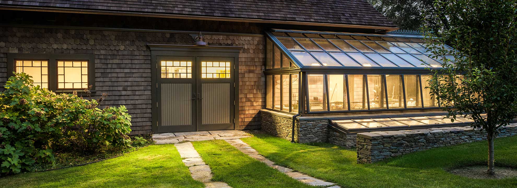
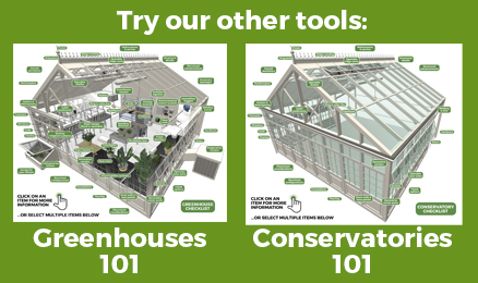
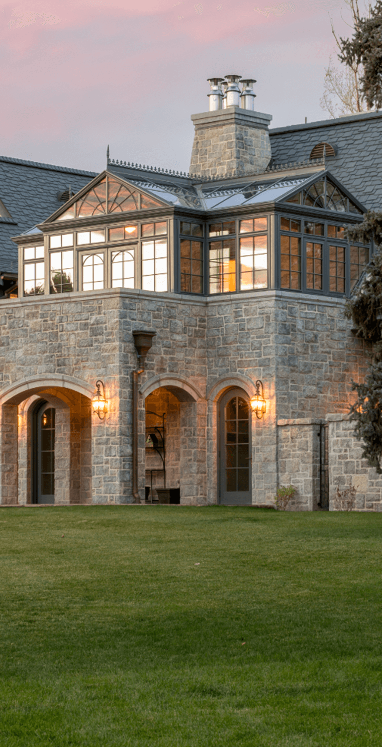
Glass Structures
- Greenhouses
- Conservatories
- Sunrooms
- Pool Enclosures
- Pool Houses
- Canopies
- Walkways
- Wood Conservatories
- Wood Sunrooms
- And More
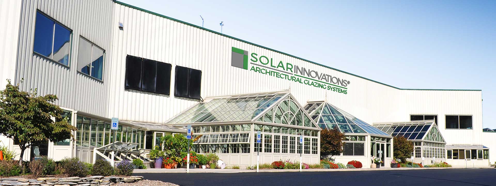
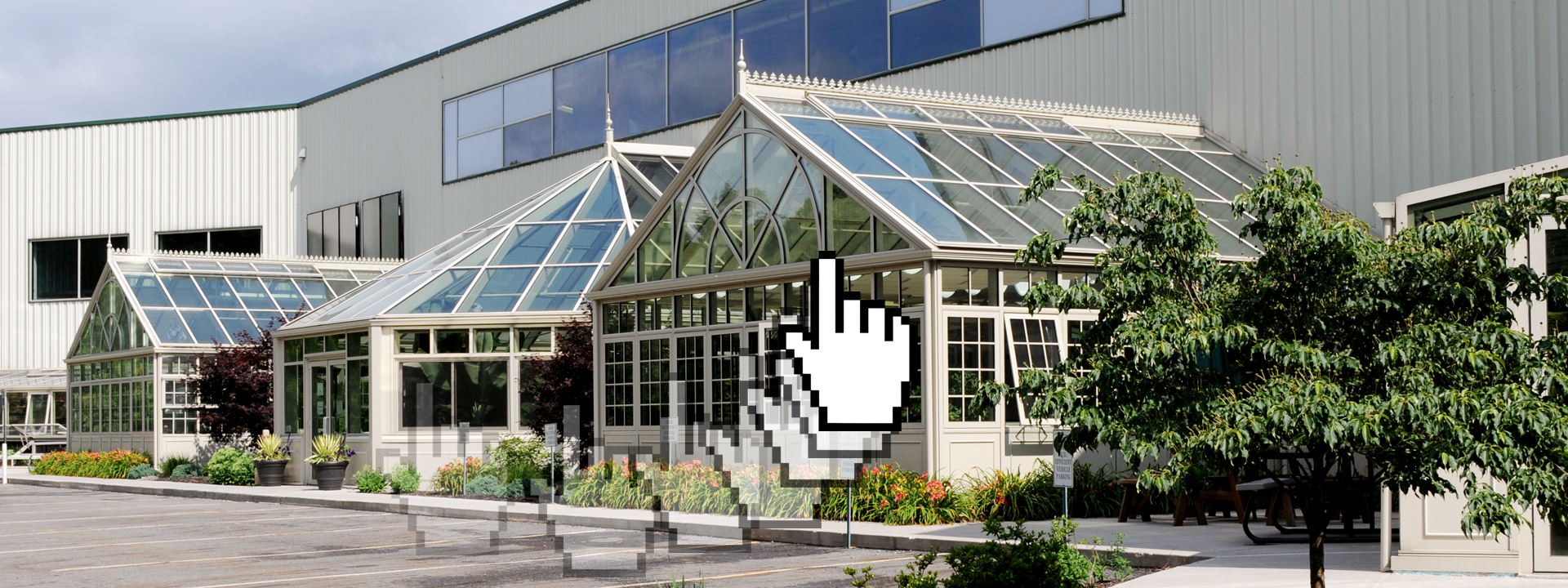
As one of the premier structure providers in the country, Solar can build any type of custom structure for both residential and commercial applications.


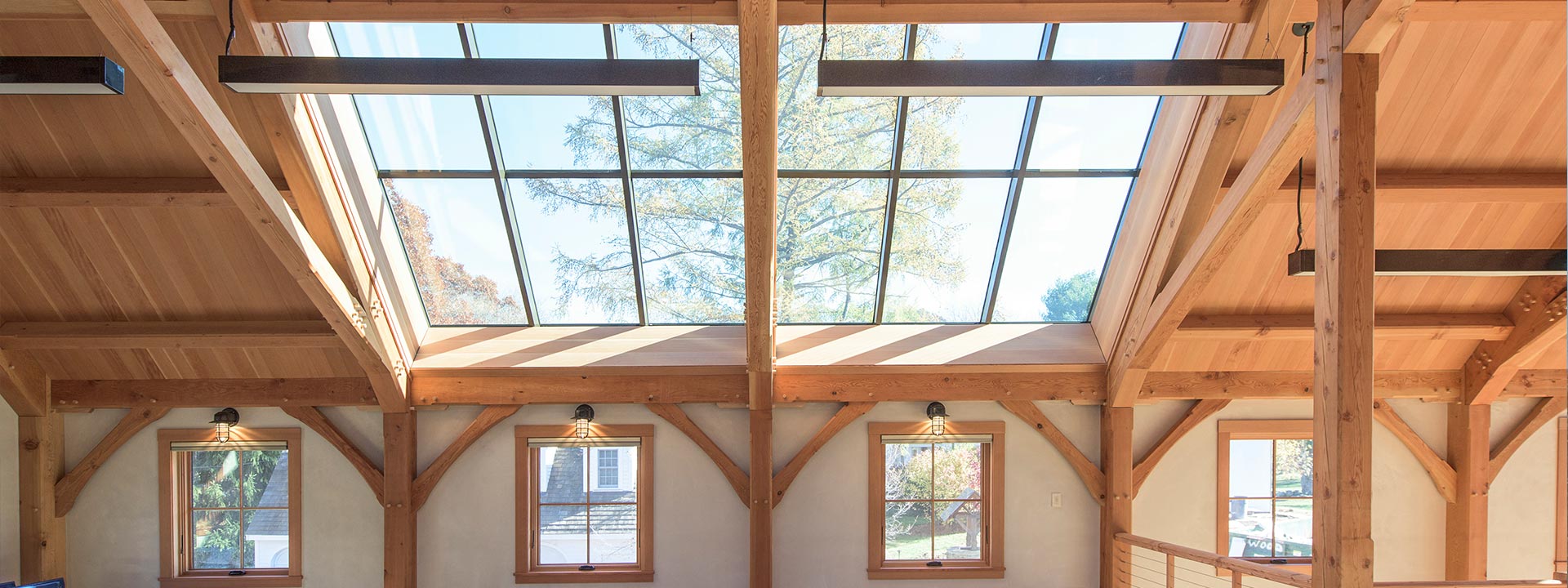
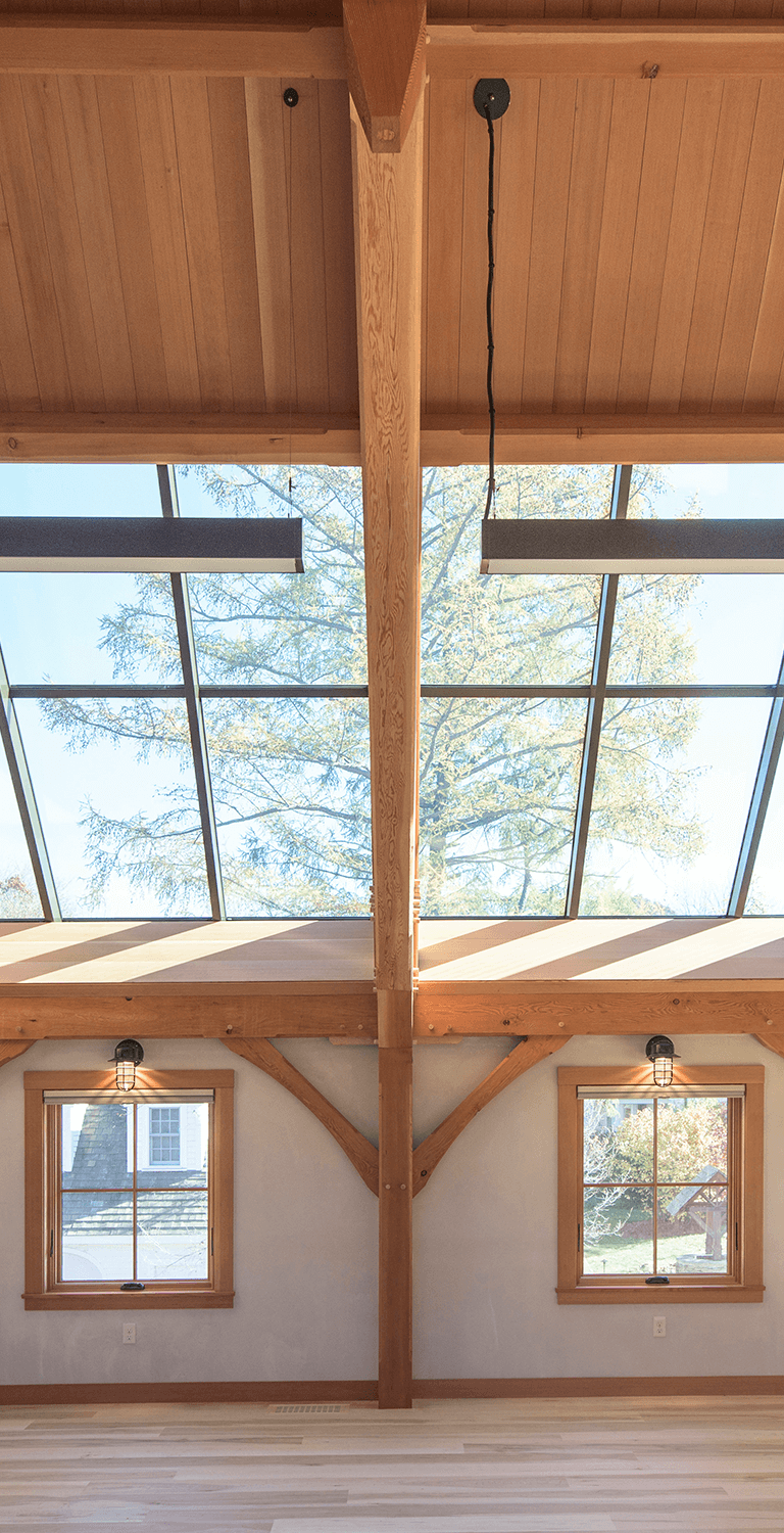
Skylight Systems
- Fixed
- Operable
- 90° Operable
- Retractable
- Ridge Vent
- Venting
- Curb Mount
- Walkable
- Roof Lanterns
- Dome
- Pyramid
- And More
Skylights are a staple product at Solar Innovations®. With our superior structure knowledge, we create some of the best “from above” openings on the market.


Industry Professionals
Download our Specifications and BIM Objects at:
Aluminum

Every product line from Solar is available in aluminum. Aluminum products are some of the strongest in the industry and are recognized for their sustainable nature and ability to support larger sizes. The durability and longevity of aluminum is what makes it a superior product when compared to other materials. We provide doors & windows, glass structures, and skylights in aluminum.
Solid Wood

The warmth and beauty of solid wood can complement any home or commercial space. Solid wood is available in a variety of species and finishes on select door and window, structure, and skylight products. For products that will come into direct contact with the elements, durable aluminum cladding is available for the exterior of your product.
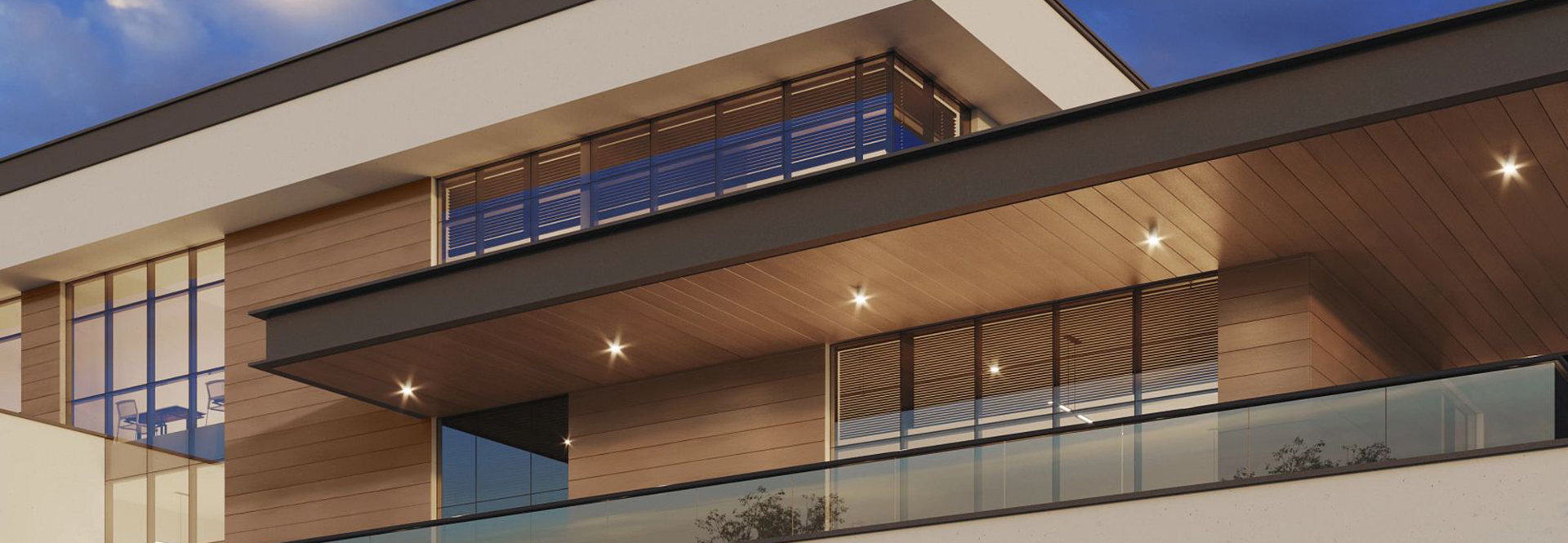
Wood Cladding & Veneering

For those interested in combining the strength of aluminum and the natural beauty of a wood interior, wood cladding and veneering are a great choice. Wood cladding is a thick wood cap on the interior of a product, while wood veneering is a thin layer of wood that adheres to it. Both options provide the beauty of real wood and the longevity of an aluminum product.
A beautiful, durable, and sustainable way to preserve your design while protecting our planet.
Get In Touch
Get in touch with our knowledgeable sales team and learn more about how Solar Innovations® can help you with your next project.