2.01 ACCEPTABLE MANUFACTURERS
A. Product based on Solar Innovations, Inc. Greenhouse Systems, as provided by:
Solar Innovations, Inc.
31 Roberts Road
Pine Grove, PA 17963
Phone 800-618-0669 / Fax: 800-618-0743
Email: skylight@solarinnovations.com
Website: www.solarinnovations.com
***Note to Specifier: Select one of the following two paragraphs; coordinate with requirements of Division 1 section on product options and substitutions.
B. Substitutions not permitted
C. Requests for substitutions will be considered in accordance with provision of Section 016000
2.02 GREENHOUSES
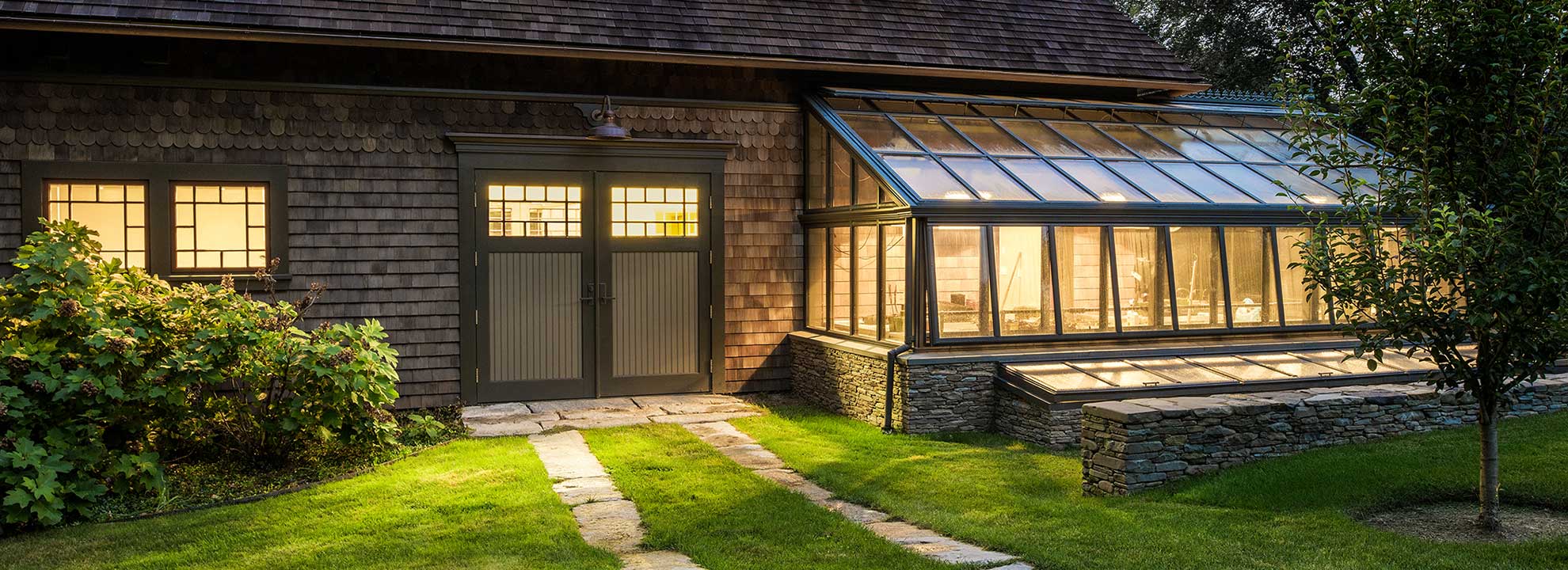
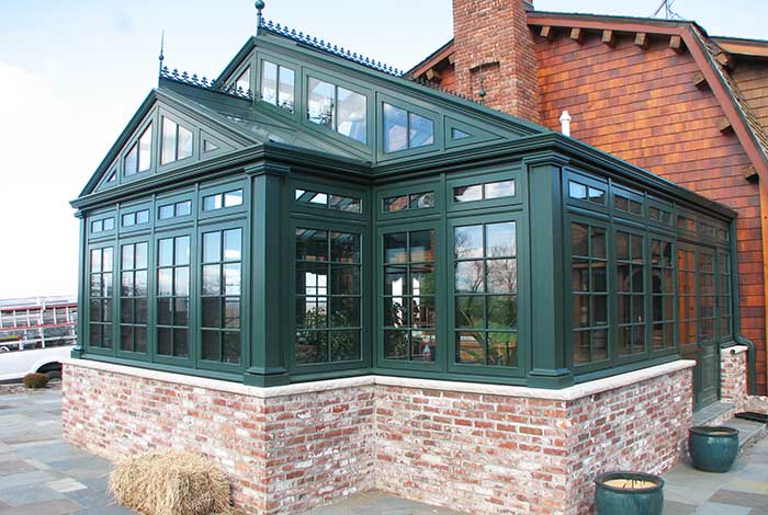
A. Greenhouse – SI5004
a. Dimensions
(1)Width – _____
(2) Length – _____
(3) Projection – _____
(4) Ridge Height – _____
***Note to Specifier: Through use of custom curves composed of laminated glass, custom curved eave structures can be provided with roof pitches varying from a 2/12 to an 8/12 and can meet any specified length. Straight eave enclosures can be designed with any roof pitch from 2/12 to 12/12 or greater.
(5) Roof Pitch – _____
(6) Eave Height – _____
b. Configuration
***Note to Specifier: Select one of the following two paragraphs
(1) Straight Eave
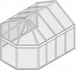
(2) Curved eave
***Note to Specifier: Select one of the following two paragraphs
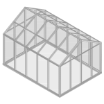
(3) Double Pitch/ Even Span
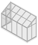
(4) Lean-to
***Note to Specifier: Consult manufacturer prior to completing this section of the specifications to verify glass solution matches intended application and safety requirements (laminated layers) of product. The manufacturer will select the type of glazing for the project based on project location, site, use of structure, and input from the Architect. If glazing type has been determined, modify the following to indicate type, thickness, tint, and other specific requirements.
B. Glazing
1. Single pane glazing options (define variances between sloped and vertical glazing as needed.)
a. 3/16″ (5mm) float glass
b. .” (7mm) float glass
c. Polycarbonate
d. Other: __________
2. Double pane glazing options (verify variances between sloped and vertical glazing as needed.)
a. 1″ insulated glass unit
(1) Outboard glazing lite – 3/16″ tempered clear glass with LoE 272 low-emissivity coating on surface two
(2) Air spacer – Stainless Steel spacer with dual seals of polyisobutylene/silicone and filled with argon gas
(3) Vertical inboard glazing lite – 3/16″ tempered clear glass
(4) Sloped inboard glazing lite – 5/16″ annealed clear laminated glass with an .060PVB interlayer
3. Specialty glazing options (job specification sections can be provided for the following specialty glazing options.)
***Note to Specifier: Discuss all specialty glazing options with the manufacturer to determine viability, benefits, and recommended installation locations.
a. Electrochromic Glass – glazing system that can be controlled through a building automation system, greenhouse automation system, or manually; shading, glare, and HVAC can all be controlled.
b. Thermochromic Glass – glazing system that is ‘tinted’ via natural heat
4. Glazing Accessories
a. Decorative Mullions
b. Interior Grids – 3/16″ x 5/8″ (4.76mm x 15.87mm)
c. Simulated Divided Lites – 3/8″ x 5/8″ (9.52mm x 15.87mm)
d. Applied Grids
(1).” traditional grids
(2) 1 .” traditional grids
(3) 7/8″ colonial grids
(4) 7/8″ ogee grid
(5) .” low profile grid
e. Decorative Raised Panels
C. Framing Members
a. Framing Members – Aluminum
***Note to Specifier: Select paragraphs appropriately. Consult manufacturer to determine which framing meets project specific requirements.
(1) SI5204 – LD System – 2″ (50mm) by:
1. 2″ (50mm), not including glazing depth.
2. 2 13/16″ (71mm), not including glazing depth.
3. 5 .” (139.7mm), not including glazing depth.
4. 8″ (203.2mm), not including glazing depth.
(2) SI5204I –I-Beam System – 2″ (50mm) by:
1. 2″ (50mm), not including glazing depth.
2. 2 13/16″ (71mm), not including glazing depth.
(3) SI5204R – Restoration System – 2″ (50mm) by:
1. 2″ (50mm), not including glazing depth.
(4) SI5254 – HD System – 2 .” (63.5mm) by
1. 4″ (101.6mm), not including glazing depth.
2. 6″ (152.4mm), not including glazing depth.
3. 7″ (177.8mm), not including glazing depth.
4. 8″ (203.2mm), not including glazing depth.
(5) Framing Member Cross Section – As required to accomplish performance criteria.
(6) Framing Member Cross Section – _____
***Note to Specifier: The following is applicable only on curved eave even-span structures. Standard bay width options are for 14.75° pitches. 30.5″ bay centers are the only option available for 30° pitch.
a. Bay Centers
(1) Bay Centers – 30.5″ (774.7mm)
(2) Bay Centers – 38″ (965.2mm)
(3) Bay Centers – 46.5″ (1181.1mm)
(4) Custom Bay Centers: ___
***Note to Specifier: Select accessories desired for structure. All accessories must be included in submitted architectural drawings.
D. Accessories – all operable accessories must include a thermal break
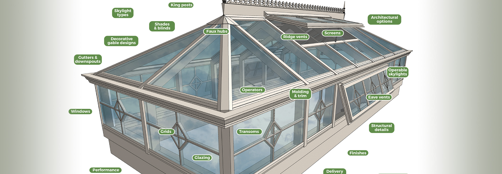
a. Awning Windows (Must be thermally broken)
b. Casement Windows (Must be thermally broken)
c. Operable Skylights (Must be thermally broken)
d. Terrace Door (Must be thermally broken)
e. French Doors (Must be thermally broken)
f. Pivot Windows (Must be thermally broken)
g. Tilt Turn Windows (Must be thermally broken)
h. Hopper Windows (Must be thermally broken)
i. Appliques
j. Corners
k. Corner Posts
l. Ridge Crests
m. Moldings
n. Decorative Crown
o. Decorative Gutter
p. Palladian
q. Trims
r. Grids
s. Finials
t. Transom Band
***Note to Specifier: Provide the design intent of the mullions here or as indicated on the Drawings. For instance, the design may call for the use of mullion to break up the glass to match the pattern on an existing structure. Any type of guideline for design the Architect can provide will assist the manufacturer in a workable design solution. Select one of the following options or modify to reflect actual design intents. Obtain the manufacturer’s approval of design shown on Drawings.
u. Mullion and Purlin Design
(1) Basic Mullion and Purlin Design – Uniform bay widths; dimension as recommended by manufacturer.
(2) Basic Mullion and Purlin Design – As indicated on the Drawings.
***Note to Specifier: Many code jurisdictions have their own local code requirements. Provide local code requirements under which the project is being designed; i.e. Uniform Building Code, 1997 Edition with local amendments. If project location is only national code jurisdiction, indicate as such.
E. Local Code Jurisdiction – ______
2.03 GREENHOUSE OPERATIONS EQUIPMENT
A. Ventilation 1. Eave and ridge vent operators – Linear actuator motors designed specifically for the vent application. Motor must be moisture resistant.
2. Horizontal air flow fan(s) (HAF) – Supply and mount fans as shown on approved greenhouse shop drawings. Size and locations is to be determined by the professional opinion of the greenhouse manufacturer and is to be shown on the approved greenhouse shop drawings.
3. Exhaust fan(s) – Supply and mount exhaust fans as shown on approved greenhouse shop drawings. Size and locations is to be determined by the professional opinion of the greenhouse manufacturer and is to be shown on approved greenhouse shop drawings.
4. Air intake shutter(s) – Supply and mount intake shutters as shown on approved greenhouse shop drawings. Size is to be matched to required exhaust fan(s).
B. Cooling
1. Evaporative cooler(s) – Supply and mount evaporative cooler(s) as shown on approved greenhouse shop drawings. Coolers to be manufacturer by Champion or Essick Air or greenhouse manufacturer approved equal and sized accordingly to structure requirements by greenhouse manufacturer. Size and models to be represented on approved greenhouse shop drawings. Greenhouse contractor will supply ducting into greenhouse based upon approved greenhouse shop drawings. General contractor is responsible for supply of mounting pad location on level ground. Wiring hookup and plumbing hookup to be provided by other trade(s).
C. Heating 1. Natural gas or LP heater(s) – Supply and mount heater as shown on approved shop drawings. Gas heater to be manufactured by Modine or greenhouse manufacturer approved equal. Gas heater to be sized and located by greenhouse manufacturer and represented on approved greenhouse shop drawings.
D. Shading System(s) 1. Vertical or sloped shade system – Supply and mount vertical or sloped shade system as shown on approved greenhouse shop drawings. Greenhouse shading system to be manufactured with Phifer Shearweave Solar shades or greenhouse manufacturer approved equal. Wiring to be provided by other trade(s).
2. Horizontal shade system – Supply and mount horizontal shade system as shown on approved greenhouse shop drawings. Greenhouse shading system to be manufactured with Phifer Shearweave Solar shades or greenhouse manufacturer approved equal. Wiring to be provided by other trade(s).
E. Lighting 1. Grow light(s) – Grow light(s) shall be designed to provide adequate lighting for approved greenhouse bench layout. Grow light(s) to be switchable ballast for both metal halide and high pressure sodium bulb units. Grow lights shall be mounted and located by greenhouse manufacturer. Grow light(s) shall be shown on approved greenhouse shop drawings. Grow lights come outfitted with molded plugs. Wiring of lighting circuit is to be provided by other trade(s).
2. Task light(s) – To be provided by other trade(s).
F. Humidification
1. Fogger(s) – Supply and mount atomizing/fogging fan(s) as shown on approved greenhouse shop drawings. Fogger(s) to be sized and located by greenhouse manufacturer. Fogger(s) shall be manufactured by Jaybird Manufacturing or greenhouse manufacturer approved equal. Plumbing and electrical hookup by other trade(s).
G. Watering system(s) 1. Drip irrigation – Supply and mount bench mounted drip irrigation system. Drip irrigation system shall be manufactured by Dramm, Phytotronics (based on final design), or greenhouse manufacturer approved equal. System shall provide adequate drippers and tool to install future drippers shall be supplied with system. Installed drippers shall be outfitted with a shut-off mechanism for the individual nozzles. Plumbing and wiring to be provided by other trade(s).
2. Misting irrigation – Supply and mount bench mounted misting irrigiation. Misting irrigation system shall be manufactured by Dramm, Phytotronics (based on final design), or greenhouse manufacturer approved equal. System shall provided adequate coverage for bench area. Plumbing and wiring to be provided by other trade(s).
H. Environmental control system 1. Environmental control system – Supply and mount a fully-functioned control system with electrical control cabinets built specifically for the greenhouse based on the approved greenhouse shop drawings. Control system shall be capable of controlling each zone independently using interior zone data and exterior data that is supplied by a weather station included in the control system. Greenhouse system shall include PC interface software package. System shall include complete electrical drawings and prints for final hook-up. Greenhouse control system shall be represented on the approved shop drawings for system mounting location. Mounting of sensors and weather station shall be the responsibility of greenhouse manufacturer. Wiring of control system, sensors, and weather station shall be provided by other trade(s). a. One day of training and on site commissioning to be completed by the control system manufacturer
I. Greenhouse Bench(es) – Manufacturer of greenhouse shall also be manufacturer of greenhouse bench system. Greenhouse benches to be shown on approved greenhouse shop drawings. If bench mounted irrigation is selected, irrigation system shall also be represented on the approved greenhouse shop drawings. Greenhouse bench layout shall be coordinated between greenhouse manufacturer and architect for final approval.
2.04 MATERIALS
A. Aluminum – 6063-T52, 6063-T6, or 6061-T6 alloy and temper. Other alloys and tempers may be used for non-structural members provided they do not void the required warranties. Indicate alloys and tempers clearly on shop drawings and in structural calculations.
1. Framing Members – Thickness based on design loading, cross sectional configuration, and fabrication requirement.
2. Aluminum Flashing and Closures – Minimum of 0.040” (1mm) thick.
3. Snap-on Covers and Miscellaneous Non-structural trim – Minimum thickness recommended by the manufacturer.
B. Insulated Panels – Expanded polystyrene; provide at all filler panels and sheet metal members.
C. Glazing – See Product Section
D. Glazing Gaskets – Compression type design, replaceable, EPDM, complying with ASTM C864, with solid strand cord to prevent shrinkage.
1. Completely compatible with glazing sealant to be used
2. Profile and hardness as necessary to maintain uniform pressure for watertight seal
3. Manufacturer’s standard black color
E. Flashings – Sheet aluminum, same finish as for system components; secured with concealed fastening method or fastener with head finished to match; thickness as required for conditions encountered.
***Note to Specifier: Verify with manufacturer if internal reinforcing is required based on framing material, size, and configuration.
F. Internal Reinforcing
1. ASTM A36/A36M for carbon steel; or ASTM B308/B308M for structural aluminum
2. Shapes and sizes to suit installation
3. Shop coat steel components after fabrication with manufacturer recommended primer
G. Setting Blocks, Edge Blocks, and Spacers – As required by manufacturer and compatible with insulated glass where required
H. Structural Glazing Sealant – Manufacturer’s Standard; black
I. Perimeter Sealant – Manufacturer’s Standard color to match framing finish if available, otherwise color as selected from manufacturer’s standard range
J. Anchors and Fasteners
1. Aluminum and Stainless Steel of type which will not cause electrolytic action or corrosion
2. Zinc cadmium-plated fasteners may be used if acceptable to manufacturer.
3. Finish exposed fasteners to match aluminum frame
K. Accessories – Provide accessories as schedule to achieve design intent and environmental control.
2.05 FINISHES
***Note to Specifier: Select one of the following frame finishes. If more than one finish is required, indicate the locations where each is to be used on the architectural drawings.
A. Aluminum Finishes
1. Unfinished Aluminum: Mill
2. Aluminum Finish: Anodized complying with AAMA 611
a. Color: Clear (Class I)
b. Color: Dark Bronze
3. Aluminum Finish: AAMA 2605 finish
a. Color: Manufacturer’s standard bronze color
b. Color: Manufacturer’s standard Hartford green color
c. Color: Manufacturer’s standard white color
d. Color: Manufacturer’s standard sandstone color
e. Color: Manufacturer’s standard black color
f. Color: Manufacturer’s standard natural clay color
4. Aluminum Finish: AAMA 2604 finish
a. Color: Manufacturer’s standard bronze color
b. Color: Manufacturer’s standard Hartford green color
c. Color: Manufacturer’s standard white color
d. Color: Manufacturer’s standard sandstone color
e. Color: Manufacturer’s standard black color
f. Color: Manufacturer’s standard natural clay color
5. Aluminum Finish: AAMA 2603 finish
a. Color: Manufacturer’s standard bronze color
b. Color: Manufacturer’s standard Hartford green color
c. Color: Manufacturer’s standard white color
d. Color: Manufacturer’s standard sandstone color
e. Color: Manufacturer’s standard black color
f. Color: Manufacturer’s standard natural clay color
***Note to Specifier: If a custom color or a different type of finish is required, verify availability with manufacturer and enter a description below.
6. Aluminum Liquid Finish: ____________________
7. Aluminum Powder Finish: ____________________
8. Aluminum Anodized Finish: ____________________
9. Metal Cladding: ____________________
10. Equipment Finishes – All related greenhouse equipment shall be per original manufacturer’s original finish. Equipment shall not be painted to match greenhouse finish to preserve equipment form, fit, looks and original warranty.
2.06 FABRICATION
A. Fabricate components in accordance with the shop drawings approved by the architect.
B. All major fabrication shall be done at the manufacturing location and not onsite.
C. Manufacturer shall remove all burrs and rough edges prior to finish application.
D. Install all gaskets and tapes at factory, as reasonable.
E. Disassemble only to the extent necessary for shipping and handling limitations.
F. Manufacturer shall be notified of any field modification prior to the activity commencing.
G. All welding shall comply with standards set forth by the American Welding Society.
H. Grind exposed welds smooth and flush with adjacent surfaces before finishing; restore mechanical finish.
I. Perform all work in a method that will meet or exceed industry standards.
J. Isolation membrane materials shall be used to separate dissimilar metals to prevent galvanic corrosion/action between materials.
K. Fabricate components to allow for accurate and rigid fit of joints and corners. Match components carefully ensuring continuity of line and design. Ensure joints and connections will be flush and weather tight. Ensure slip joints make full, tight contact and are weather tight.
***Note to Specifier: Select the following if internal reinforcing is required for this project.
L. Steel Components
1. Clean surfaces after fabrication and immediately prior to application of primer in accord with manufacturer’s recommendations.
2. Apply specified shop coat primer in accord with manufacturer’s instructions to provide 1.0 mil (0.05mm) minimum dry film thickness
M.Fabricate components true to detail and free from defects impairing appearance, strength or durability.
N. Provide contoured exterior horizontal or purlin glazing retainers to minimize water, ice, and snow buildup.
O. Reinforce components at anchorage and support points, joints, and attachment points for interfacing work.
P. Accurately size glazing to fit openings allowing for clearances as set forth by the “Glazing Manual” published by the Flat Glass Marketing Association (FGMA).
Q. Cut glass clean and carefully. Nicks and damaged edges will not be accepted. Replace all glass with damaged edges.